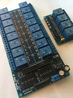
As described in my previous posts, I now have a pair of 8 relay boards from ControlEverything.com controlled by Alexa, an iOS app, and other Patriot devices. So now its time to get to work and actually install the boards and wire them up to the first control panel.
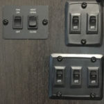
The front control panel in my RV contains the most switches, so I’m going to start there.
The top part contains switches for the vent (open, close, fan) and 5 other lighting switches. So I’m going to need 8 relays.
- Vent fan
- Vent Open
- Vent close
- High counter lights
- Low counter lights
- Sink handing lamps
- Kitchen ceiling lights
- Left side trim lights
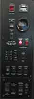
The lower section has a bunch of controls and indicators on it, but I’ll only be automating 7 of the switches:
- Ceiling lights
- Door side outside floods
- Opposite door side outside floods
- Front porch floods
- Front awning LEDs
- Front awning extend and retract
So I pulled each panel to see if there is room behind it for the 3″ x 7″ x 1″ boards. Unfortunately there is a water pipe hidden in the midst of all those wires that prevents pushing them back out of the way.
 So my next step was to pull the entire panel as shown. This requires removing 8 screw covers and screws, and then loosing or removing some of the individual control panel screws because they went all the way through to the wood behind the panel.
This is where having a very supportive wife helps, because it looks pretty scary at this point.
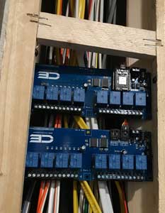
Once removed, I could see that there was a ton of room in the bottom section, and sufficient room in the top section. After positioning the boards various ways in those sections, I realized that the bottom section would easily work, but the wire runs would be pretty long. So I considered using the top section, then realized that the boards would fit at the top of the 2nd section, simplifying routing of the wires.
So here you can see the boards mounted inside the wall behind the panel. The sides angle inward, so I was able to run a few screws through the holes in the corners of the boards to fasten them. Just by luck, the width of the opening is enough that I can get to the wire screw connectors on the boards.
So once the boards were mounted and 12v power applied, I could test the Alexa interface.
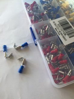
So next I just needed to connect the relays to the 15 switches. The screw terminals are easily accessible, so it’s a matter of just connecting the piggyback terminals and hooking up the 15 wire pairs.
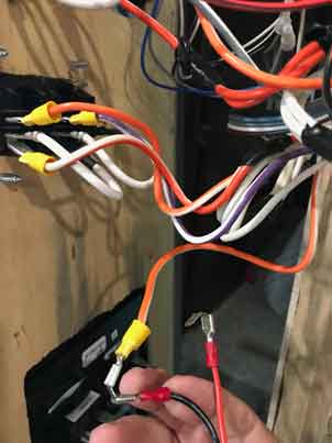
So for each switch:
- Attach a pair of wires to the normally open (NO) relay terminals
- Attach a piggyback connector to each wire
- Remove the connector from the switch
- Attach the wire that was going to the switch to the piggyback connector that has the relay’s wire connected to it.
- Attach the piggyback connector to the switch.
The result is that the relay is connected in parallel to the light switch, and no wires have been cut.
So after attaching the first relay, I did a quick test with Alexa, and nothing happened. What? I could see the LEDs coming on, I could hear the relay flipping, but the light wasn’t coming on. So after about an hour of measuring the relay terminals, trying other relays, scouring the forums, whining and moping around, I finally figured out that the relays are mislabeled on the Photon 8-Relay board. Relay 1 is actually labeled relay 8. They’re backwards right-to-left instead or left-to-right. So I moved the wires from relay 1 to relay 8, and its working now.
Armed with this new information, I completed hooking up the other 14 relays, and now I can control most of the lights in the main room, the powered vent, about half of the outside lights, and the front awning and its LED strip lights.
Now I’m ready to order a couple more ControlEverything boards so I can tackle the smaller, rear control panel.