I’ve started replacing the lighting wall switches in my RV. Instead of hard-wiring the switches to the lights, I’m using radio connected Arduinos. The switches will appear to work the same, but what is really happening is that the switches are read by an Arduino, that then sends information over radio to another Arduino to control the LED light.
So why all the extra cost and complexity?
To begin with, the cost is not very much. The parts I’m working with amount to about $10 per board. As for the complexity, I have several objectives:
- Enable dimming of the lights
- Enable grouping of lights
- Enable remote control
This last one is the exciting part. Once I get the internet connection working, I’ll be using my Amazon Echo to voice control the lights.

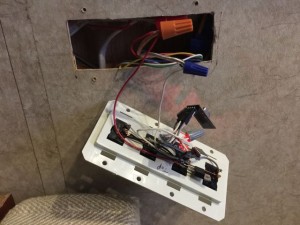
So, where am I in this process? I had initially cobbled together a wall switch to remotely control ceiling lights over my desk.
As you can see in the picture, this was pretty fragile, with parts soldered directly to the switch pins. I had to resolder things after breaking things when installing it into the wall. This was part of my motivation for creating custom printed circuit boards.

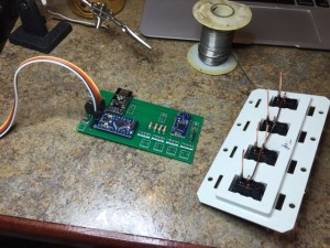
In this photo you can see the new 5cm x 10cm PCB I created for mounting to the wall switches. On this board I’m not going to use any of the 4 LED driver circuits, so they are unpopulated.

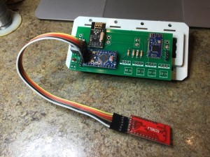
And here you can see the new PCB mounted to the switch. The FTDI programmer is connected to the Arduino for programming. It will be disconnected when I install the board into the wall. The nice thing about this arrangement is that it simply mounts into the wall like any other light switch.
The small blue board on the right side is an HM-10 Bluetooth LE part. This provides BLE communication and Beacon capability. This was my first attempt at surface mount soldering. Total cost on this board, including PCB, was about $7.50.
